Åke's Oxygen Fuel Cell Description and Dissection Page
Oxygen Analyzers - Principle of Operation (Electro-Chemical or Galvanic Fuel Cell Sensor)
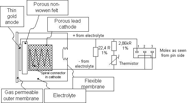
The oxygen diffuses through the membrane into the into the sensor is reduced to hydroxyl ions at the gold cathode. The rate of the chemical reaction is in general limited by the diffusion rate through yhe membrane, not the reaction per se.
O2 + 2H2O + 4e- ----> 4OH-
The hydoxyl ions thus formed oxidize the lead (or zinc) anode:
2Pb + 4OH- ----> 2PbO + 2H2O +4e-
This yields an overall cell reaction of:
2Pb + O2 ----> 2PbO
The fuel cell oxygen sensor is a current generator. The amount of current generated is proportional to the amount of oxygen consumed. Many sensors include a shunt resistor and a temperature compensating network with a thermistor so as to provice a voltage output proportional to the oxygen partial pressure
Another tear-down of a fuel cell can be found on Mark Munros' page @ http://www.ppo2.com/K1d_dissection.htm
|
Schematic description of an R22/R24 medical fuel cell. |
|
Oxygen Fuel Cell dissection |
|
|---|---|
|
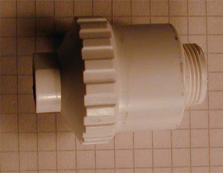
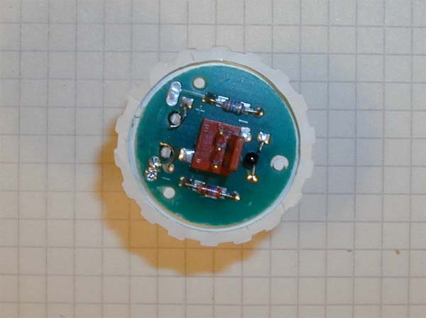
The victim on the slab avaiting dissection. The cell is an R22 / R24 equivalent. The exact details of the cell varies from manufacturer from manufacturer but the general parts remain there. |
|
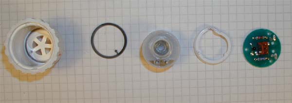
from right to left:
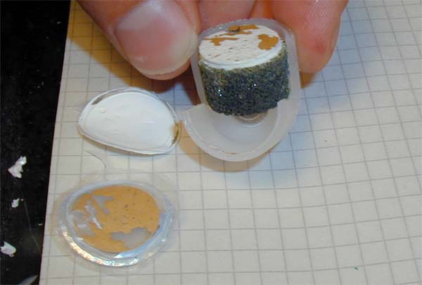
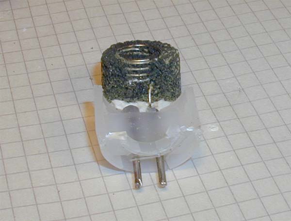
Housing, sealing, electrolyte chamber ( more details below), locking ring and resistor/thermistor network and connector. |
|
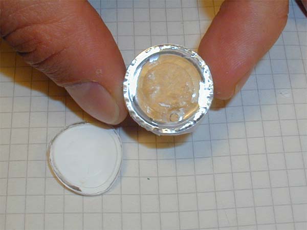
Close up of the solderside of the printed circuit board and the top of the electrolyte chamber. Note the metal rods in the upper part of the electrolyte chamber that are used to conect the electrochemical cell to the circtuit board. Note also the thinner depression in the middle of the electrolyte chamber that is a flexible membrane allowing expansion of the elctrolyte without stressing the gas permeablemembrane on the other side. |
|
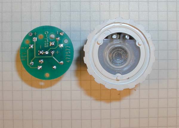
Component side of the circuit board. One notes immediately that the distance from the electrolyte to the thermistor (black blob to the right of the molex connector) is quite long and that the time neeed for the thermistor and electrolyte to reach the same temperature can be significant. |
 |
The electrolyte chamber cut open. Middle left the thin gas permeable membrane is seen and immediately below the very thin gold electrode. a Thin fibrous something ensures that the anode and cathode are galvanically separated. |
 |
Close up on the gold cathode. |
 |
The porous lead anode with its spiral of stainless stell to allow good contact andconnection to teh circuit board. |
last modified 2002-07-16
All material on this website is copyright 2002-2004 by Åke Larsson. All rights reserved.