Åkes' Draeger FGG III Pictures
The Draeger FertiggasGemishGeräte III, (pre-mixed gas unit III)
also known as the FGG III is a late 1960's rebreather design. FGG III is a
semi closed constant massflow device very similar to the Drager FGT as well as
the Draeger Dolphin and Ray.
The unit is made for self-contained short duration deep diving down
to 200m. To allow longer diving times the unit is equipped with a connector for
external gas supply. The unit is intended to be used from a diving chamber or a
submarine.
The duration of the unit was as follows:
| Depth [m] |
Duration [min] |
Gas mix (%O2/%He) |
Gas flow [L/min] |
| 0 - 60m |
ca 60 |
mix "0"
Nitrox 29%O2 |
20 L/min |
| 50 - 110 m |
ca 40 |
mix "I", 17,5/82,5 |
30 L/min |
| 90 - 160 m |
ca 30 |
mix "II", 12,5/87,5 |
40 L/min |
| 140 - 200 m |
ca 20 |
mix "III", 10/90 |
50 L/min |
The mix "0" is run through the mix "III" flow
setting valve position.
The on board tanks (2 * 4L steel) are filled with a one of the
above mixes and a selector valve on the regulator/ dosage unit is set to one of
the mixes "I" to "III". The flow controlling orifices are
fixed and thus not adjustable. The FGG has a 40 bar intermediate pressure to ensure critical
flow over the orifices at all depths (see the flow theory pages).
Worth to note is that all connectors can be removed without any
tools, all have
radial O- ring seals except the tank fitting.
For more information on the older Draeger devices try to find the
excellent book - "Tauchtechnik" by Gerhard Haux, Springer Verlag 1969, Library of congres no:
79-99015. The book is in German.
The figures in the table above originate from the FGG service
manual (thanks Jason M in Oz) and differ slightly from those found in
"Tauchtechnik"
Jason McHattan has converted his FGG into a full CCR unit, see the http://www.trimixdivers.com/fgg/
and http://www.deepdiving.net/fgg/fgg.html
The unit shown on the pictures below has never been dived and IS
NO LONGER FOR SALE. The seller made up his mind to keep this piece of unique
diving gear!
 |
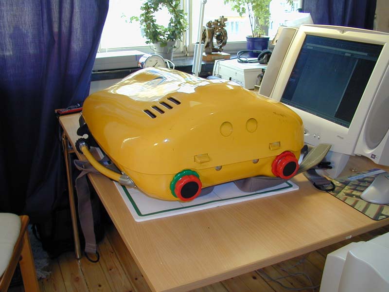
The unit with cover on. A rubber strap hold the cover in
place.
The yellow hose with a black rubber knob on the right side of the unit
is the off-board gas connector. The off- board connector feeds directly
into the fresh gas line into the circuit thus making it possible to
control
the fresh gas flow (and mix) externally. See also picture below.
|
 |
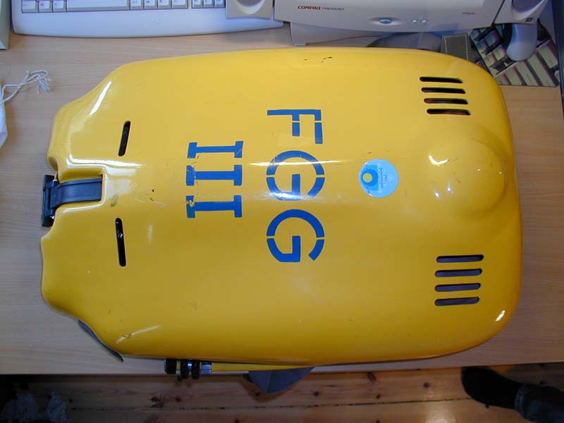
The unit seen from the top. The yellow hose to the left is the
off-board gas supply connector. The breathing hose connectors are colour coded and
do also have different threads. The protective caps have the wrong colour
though. |
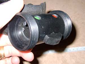 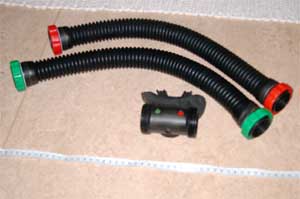 |
Two rather crappy pictures of the DSV and hoses of the FGG /
FGT.
The non-return valves are housed in the hoses. The DSV is very similar
to the one found on the Draeger Ray.
The threads and connection sizes are different thus makin
mis-connection impossible also for the colour vlind. |
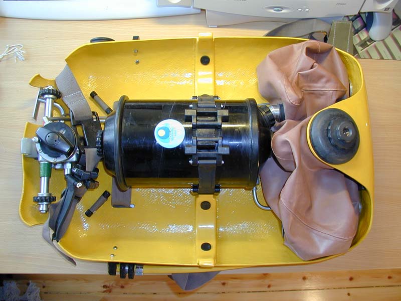 |
Without the cover, from right to left:
- Overpressure dump valve,
- Exhalation bag (below)
- Inhalation bag (above)
- Radial canister with lid to the left
- Space for 4L steel tanks above and below
- Pressure reducer and flow control unit with gas selector valve
The rubber straps that hold the tanks are missing but are similar to
the one holding the upper cover. |
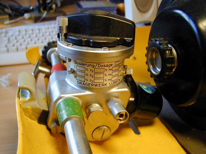 |
Regulator and with dosage selector valve. Note the selection
locking
bolt and the intermediate pressure over pressure relief valve. Also seen to the right is the
screw that closes the canister. |
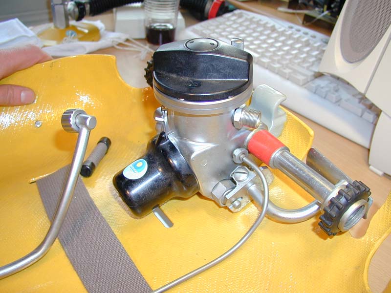 |
The other side of the regulator with bypass valve (under
the tank connector), HP line to pressure gauge, and dosage line
(disconnected). |
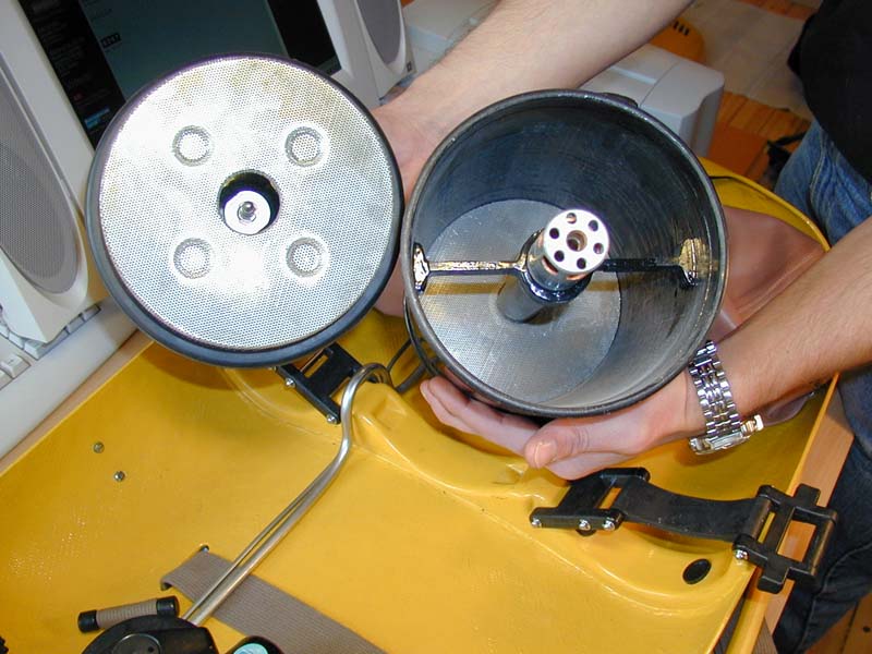 |
Inside of the canister, After 1 use it no longer shines!
Exhaled gas flows down in the inner tube, turns upward through the mesh and then
through the lime and into the inhalation bag. The canister has an axial flow path. |
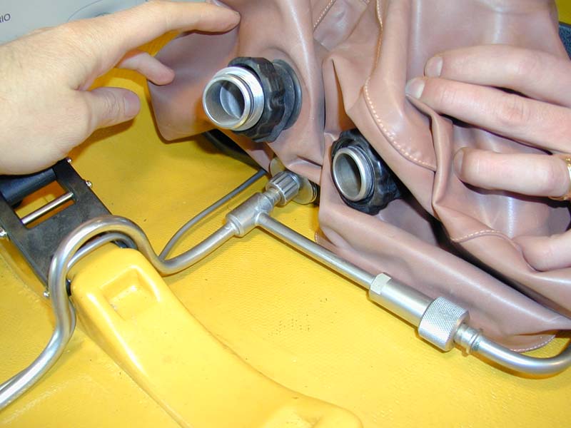 |
Inhalation bag (top) and exhalation bag (bottom) connectors
to the canister. Also seen is the fresh gas supply coming from the on-board
tanks from the left and the off-board via a non-return valve from the
lower right.
The off board gas supply is a low pressure feed. |
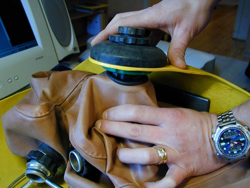 |
The over pressure dump valve is connected to the exhalation
bag. It is adjustable between 7 and 11 cmH2O. The connection between the exhalation bag and the canister holds a water trap, a 10 cm
tube located inside the bag. |
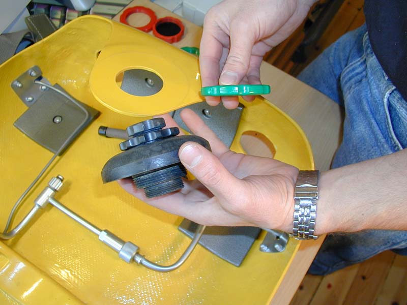 |
Over pressure valve, from top left:
- Pressure release adjustment knob
- Locking nut
- Valve body
- Thread for mounting in unit (fits the green nut)
- Thread for connection to exhalation bag.
|
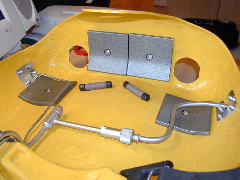 |
The almost bare lower shell which is made from glassfibre reinforced
epoxy. To the left the HP lines exits the shell to the pressure
gauge. Balancing weights, 4 *1 kg are mounted around the bags. The harness
shoulder straps are fed through the shell and secured with a plastic
pin. The off-board gas line exits into the yellow hose with black
knob seen in
pictures above. |
| ManualFGG.pdf
SparePartsFGG.pdf
Description FGT 1A.pdf |
The FGG description in PDF format
The FGG Spare parts list and schematics
The operators manual for the FGT 1/A |
Last updated 2002-09-12
Return to Main
Page
All material on this website is copyright 2002
by Åke Larsson. All rights
reserved.