Åkes' Analogue paramagnetic oxygen analyser(s)
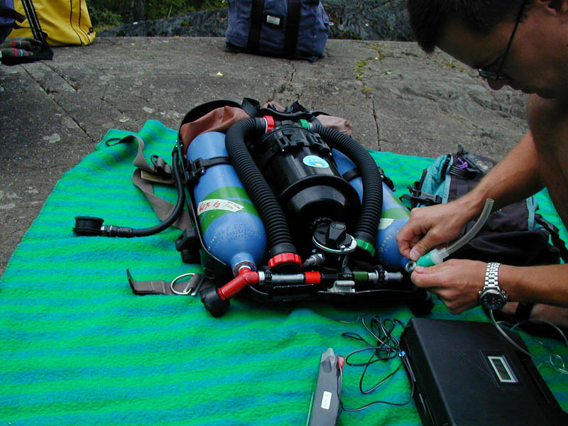
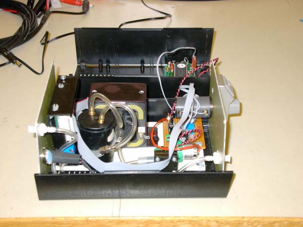
This is my personal unit that I have used in the field 1997. The sealed lead-acid battery (12V 3 Ah) seen in the picture is definitely overkill.
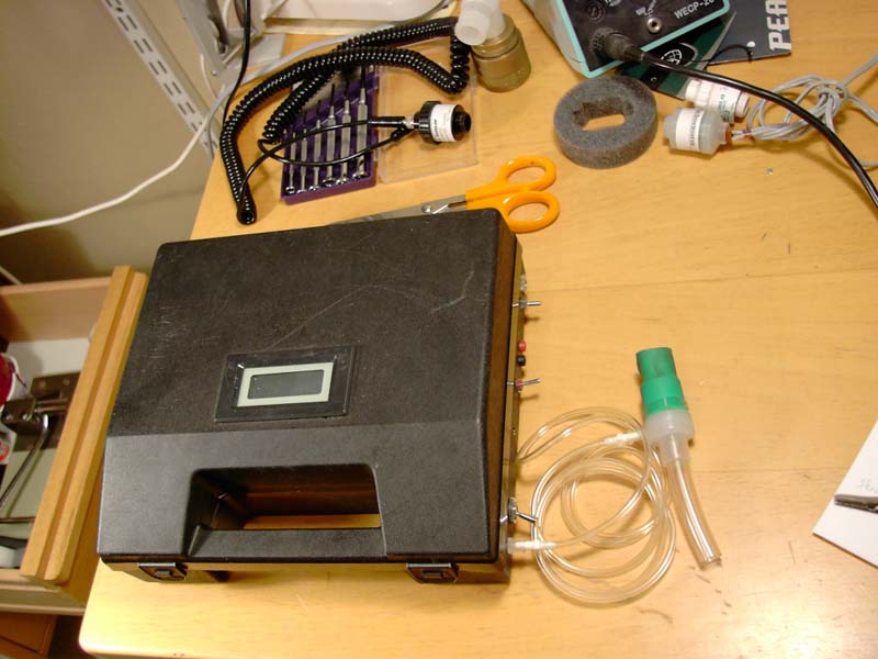
On the outside you see the DVM on the top of the box. On the right side you see (from top of the picture towards button) power inlet, gas outlet, analogue out, pump on/off switch, calibration potentiometers (hardly visible), measurement range selection switch, and gas sample inlet.
Inside you see:
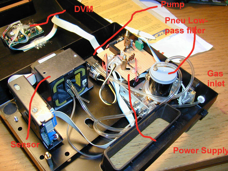
Close to the gas inlet you find the measurement range selector, 0 to 20% or 0 to 100 % O2.
The unit has an electrical schematic as follows:
The sensor needs +5V, -5V, and gnd, the LCD DVM (UP5035) needs to have a supply gnd separate from measurement gnd, this is accomplished with a switched converter (TMA1205D).
The pneumatic schematic is as follows. Note that the sensor is a partial pressure sensing device and that the pressure variations generated from the sampling pump will disturb the reading unless they are filtered out. A pneumatic low-pass filter (a reservoir and a restrictor) takes care of that.
There are other designs as well:
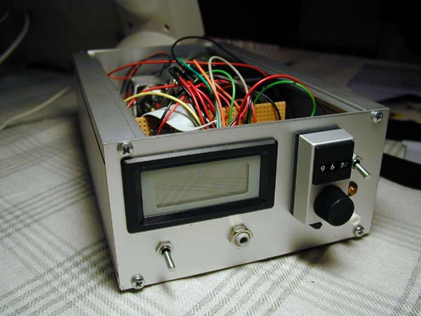 |
The front with DVM, pump on/off switch, precision pot for gain adjustments, small precision pot for zero / Offset adjustment as well as gas inlet port. |
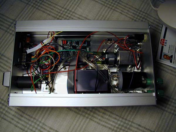 |
Inside of the unit: from left to right:
- DVM and potentiometers, |
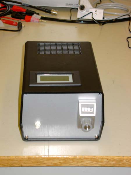 |
The front with DVM, gain adjustement potentiomenter, and gas
inlet port.
Offset adjustment is only needed when the unit is assembled so that pot is hidden inside. |
 |
The crowded inside - from left to right:
- Power in and gas out, |
Last modified 2002-07-15
All material on this website is copyright 2002 by Åke Larsson. All rights reserved.