Åke Larsson, Stockholm, Sweden, 23rd April 2000
If you need more info, contact Interspiro on the address below or the author at ake.l@home.se.
All material on this website is copyright 2002 by Åke Larsson. All rights reserved.
The following text is written under the assumption that the reader has knowledge about the relation between gas fractions and partial pressures as well as basic knowledge in rebreather design. Also, nitrox concepts like MOD and EAD are assumed to be familiar to the reader.
Contents
Some
introductory comments
Some
things about the Company and its history
Some
Physiology
Some
Semi Closed Rebreather Theory
Some
Comments about the DCSC concept
The
backpack and the rebreather unit
Some
comments on the breathing circuit
The
hydrostatic imbalance compensated spirometric bellows
The
scrubber
The
dump valve
Some
comments on the pneumatic system
Fresh
gas addition
DCSC
fresh gas addition theory
The
Warning System
The
hydrostatic compensation
Duration
Some
concluding remarks.
Some
references and further reading.
Some
Internet Links
Some things about the Company and its history
Interspiro, formerly a division of AGA, has been making breathing systems for water, chemical, and smoke diving since the 1950’s. Among the products one will find the AGA divator open circuit breathing systems Mk 1 and Mk 2, the latter being used in a modified version by the US air force for smoke and chemical diving. The most noticeable design features of these compact units are the excellent breathing, their cold water performance, as well as the fact that gas cylinders are mounted upside down. The latter being a feature rather easy to like once one have been introduced to it, cylinder valves and reserve valves being possible to reach without breaking ones arms. See the http://www.interspiro.se/divator.html.
The Interspiro rebreather range has so far been exclusively targeted at the military market.
The first rebreather product of Interspiro was the ACSC, Alternating Closed and Semi-Closed rebreather. The ACSC was developed and introduced to the market in the early 1980´s. The ACSC was designed for mine counter measures and was anti magnetic with a very low acoustic signature.
The ACSC design was tested for deep diving operations and experimental units have been tested at depths down to 450m, see [1].
In the early 1990´s the ACSC was further developed into the DCSC, Demand Controlled Semi-Closed rebreather, still for mine counter measure use. The design is in many ways innovative and differs on some major point from most other RB designs.
Both the ACSC and the DCSC has been sold on the international market.
Interspiro also manufactures the Oxydive, a chest mounted demand controlled O2 CCR for combat swimming, see Figure 1 below.
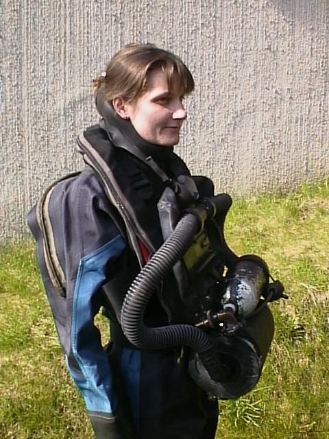
Figure 1. The Interspiro Oxydive - O2 CCR, check http://www.interspiro.se/product-oxydive.htm
Last but not least, Interspiro is probably best known as manufacturers of the Interspiro full face mask. The mask is available both in an open circuit version and a rebreather version used among other things for the DCSC. Also available from them is a wireless communication system for use with the FFM.
In a human body in steady state work, i.e. during aerobic working conditions, the relationship between the minute ventilation, VE (the sum of tidal volumes over a minute, sometimes denoted RMV), and oxygen uptake, VO2, is about constant. The ratio of minute ventilation and oxygen uptake is often called the extraction ratio, here denoted KE.
![]() Eq.
A
Eq.
A
The extraction ratio falls in the range 17 to 25 with a normal value of 20 for healthy humans, the variations primarily depends on the diet of the diver and the dead space of the diver and his equipment.
/* Those of you who hate physiology – skip the rest of this paragraph completely!! */
The body of a diver needs oxygen to perform its work. The breathing in a normal diver during non-exerting work (i.e. below the anaerobic threshold) is primarily controlled to maintain a certain pH, i.e. primarily the carbon dioxide partial pressure, PCO2. The PCO2 level in the body depends on the alveolar ventilation and the CO2 production.
The alveolar ventilation is the minute ventilation minus the wasted dead space ventilation, the latter is normally less than 30% of a normal breath.
The ratio between the CO2 production and the oxygen consumption, is called the respiratory quotient, is usually assumed to be slightly below 1 but varies between 0.8 (only fat being burned) over 1 (pure carbohydrates) depending of what kind of substrate is being burned.
During excertion when the diver starts to produce lactic acid the ventilation will increase in relation to the oxygen consumption as seen in the figure below and the effective respiratory quotient will increase as will the extraction ratio.
Figure 2. Simplified graph showing the relation between the oxygen uptake and minute ventilation for a group of subjects, from [5].
The really interested reader is referred to [6], especially chapter 5 respiration and excertion.
Some Semi Closed Rebreather Theory
In a semi closed rebreather the oxygen fraction in the breathing circuit, FO2, depends on the diver's oxygen uptake, VO2, and the added flow, Qmix, and composition, Fmix, of the fresh gas as expressed in the equation below.
 Eq.
B
Eq.
B
/* Those of you who hate math – skip the rest of this paragraph completely!! */
For a semi closed rebreather the general mass balance equation is valid. Using the notation indicated in the figure below a differential equation for the change of oxygen fraction over time can be set up and solved assuming instantaneous mixing and neglecting breath to breath variations in gas concentrations. The oxygen fraction in the breathing circuit will be according to the equation D below. Note the steady state term (to the left) and the transient term (to the right). The time constant in the transient term has a strong dependency on the volume (in normal litres) of the breathing circuit.
Note: the time constant relates to the transients of the oxygen fraction of a SCR only, the time constant for fall of PO2 in a CCR is linear and not depth dependent!
Figure 3. A simplified model of the rebreather.
In the Figure 3 above the:
Fmix is the oxygen fraction of the fresh gas
Qmix is the flow of fresh gas [normal L/min]
VO2 is the oxygen uptake of the diver [normal L/min]
V is the volume of the breathing circuit [in normal litres]
FO2(t) is the oxygen fraction over time in the breathing circuit.
 Eq.
C
Eq.
C
/* The basic differential equation */
 Eq.
D
Eq.
D
/* The solved FO2 equation with steady state and transient term */
The equation will be used below when discussing the specifics of the DCSC gas addition system.
Some Comments about the DCSC concept
The backpack and the rebreather unit
The DCSC is divided into a rebreather unit and a backpack. The backpack carries the dry suit inflation bottle. The backpack is often donned already when the diver is dressed. The unit is very easily clicked on to the backpack when its time to go into the water. After dive the rebreather unit is easy to remove already in the water. The rebreather unit is released by pulling a knob and doing a rapid forward push with the hips. This feature makes it very easy to get back into a boat after a dive also when the weather conditions are unfavourable. It is possible to remove the rebreather unit underwater.
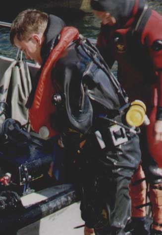
Figure 4. Entering a boat after removing the rebreather unit in the water. Note the backpack with the suit inflation bottle visible above the weight belt.
Only the breathing hoses and FFM/DSV are exposed outside the glass fibre cover of the unit. During transportation, for example in the RIB on the way to the dive site, the FFM and hoses are stored inside the cover and the unit is often used as a seat!
The breathing hoses connect to the unit rather low, at about the level of the lowest ribs. The hoses are kept low over the shoulders and also without additional weights on the hoses the drag one experiences when towed after a scooter or a boat is less than for example the Draeger Dolphin and the Carleton/Fullerton SIVA range.
The weight of the complete DCSC is in the order of 33 kg. The unit is neutrally buoyant when equipped with aluminium nitrox tank. When a composite tank is used the unit is equipped with few kilos of lead to remain neutral.
The tank valve, reserve valve, and the bypass valve are mounted low on the left side of the rebreather.
Some Comments on the Breathing Circuit
Figure 5. The simplified pneumatic diagram of the DCSC
The hydrostatic imbalance compensated spirometric bellows
The design of the counter lung is based on several patents, [2], [3], and [4]. The breathing bellows is hinged and the angle between the bottom and the top plates is proportional to the bellow volume, thus the term spirometric. The change of bellows angle is used to control the fresh gas addition system, see below.
The top plate is weighted (a design copied by the Halcyon team) which compensates for the pressure difference, about 20cmH2O, between the lung centroid and the breathing circuit. The result is a back mounted breathing bellows without the negative hydrostatic imbalance.
The weights increase the pressure in the bellows when the diver is swimming normally in prone position. When the diver is vertically positioned in the water the weight is carried by the hinges and when the diver is on his back the weights reduce the pressure in the breathing circuit thus maintaining a hydrostatic pressure in the breathing loop close to the actual pressure at the lung centroid.
The bellows is in the expiratory limb of the breathing circuit thus collecting condensate from exhaled gases as well as mask/mouthpieces leakage.
The gas is circulated from left to right, i.e. inspiration over the left shoulder.
The total gas volume of the breathing circuit is about 7L, out of which the breathing bellows make up slightly less than 4.5L.
The scrubber is located in the inhalation limb of the breathing circuit. The soda lime is packed in a plastic canister that is inserted in the canister housing of the unit. It has an inward – radial gas flow. The scrubber canister contains about 2,5 kg of sodalime.
The scrubber design has been used by other manufacturer among the Fullerton and (at least) previous versions of the PRISM (??)
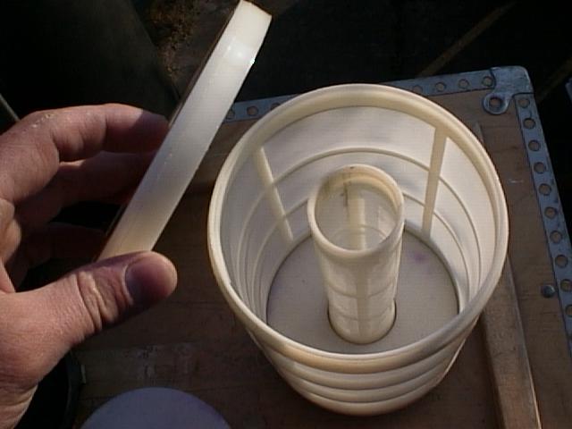
Figure 6. The scrubber canister.
The gas dump valve is integrated in the lower plate of the breathing bellows. The valve is opened when the volume of the bellow exceeds a certain limit. The work to open the valve is very small and the dump hardly noticeable compared to RB´s with pressure controlled dump valves.
Some Comments on the Pneumatic System
The DCSC carries a 5L/200bar aluminium tank mounted horizontally at hip level. The bypass control, the tank valve, and the reserve valve are mounted at hip level on the left side of the unit.
The fresh gas is added to the breathing circuit in the inspiratory limb. The addition is made by controlling the pressure in a dosage chamber proportional to the bellows position. The chamber is filled with fresh gas to its highest pressure when the bellow is in the lowest position and the pressure is lowered when the bellows rise, the gas released from the dosage chamber goes into the breathing circuit. Thus gas is added in the inspiratory limb during the divers expiration.
The result is the addition of a certain amount of gas (a certain differential pressure change in a known volume) per ventilated volume.
The volume of the dosage chamber is matched for a specific fresh gas. The DCSC uses two mixtures of fresh gas, a lean nitrox mix of 28% and a rich nitrox mix of 46%. The dosage chamber is changed when the gas is changed.
The resulting steady state oxygen reaction in the breathing circuit is about 22.5 % for the lean mixture and 37.5 % for the rich mix. Air tables are used down to 57 m with the lean mixture and EAD tables down to 30 m with the rich mix.
The DCSC can then cover the range from 0 down to 57 m still gaining better optimisation between MOD and EAD using only two gases compared to the standard constant mass flow SCR that (at least in NATO) use three different mixes for the same task, see Figure 7 below.
DCSC fresh gas addition theory
The extraction ratio was defined above and if the minute volume is expressed as a function of extraction ratio and oxygen uptake:
![]() Eq.
E
Eq.
E
The added fresh gas flow is related to the minute volume (see the paragraph above):
![]() Eq.
F
Eq.
F
where K1 is the dosage ratio depending on the dosage chamber and the pressure, the K1 is 60% for the lean mix and 30% for the rich mix.
Combining the two equations above yields:
![]() Eq.
G
Eq.
G
Inserting into the steady state term of the SC equation:
 Eq.
G
Eq.
G
From the equation above is apparent that the design has no dependency on the oxygen uptake and since the dosage ratio is selected before the dive the only variations left is due to the extraction ratio!
Figure 7. The variation in PO2 vs. depth for constant mass flow SCR versus the DCSC with lean and rich nitrox mixtures.
Each of the three light gray areas in Figure 7 above represent one of the three standard NATO mixes used for constant mass flow SCR. The upper line is the steady state partial pressure seen in the loop at low oxygen uptake, i.e. at rest. The lower line represents the partial pressure (as a result of a loop FO2 of 21%) that is the result of high oxygen uptake (2 L/min).
The dashed field represent the DCSC using lean and rich mixes, note the much smaller variation and thus much better optimisation between MOD and EAD. Also notable is that a divers with an extreme work capacity will not deplete the circuit from oxygen as can be done in the constant mass flow SCR.
If the time between two consequent additions of fresh gas is too long, the DCSC will give the diver a warning by adding a small but noticeable inspiratory breathing resistance, a small fresh gas flow is also added. It is still possible to breathe when the warning is activated. A new fresh gas addition will reset the warning. The reasons for the loss of gas addition can be several, usually it is due to the reserve valve shutting of the gas supply thus providing a warning to the diver to release the remaining gas and abort the dive. The operating procedure when a warning is activated is to check the pressure gauge and if necessary release the reserve valve. In other scenarios the diver bypasses and aborts the dive.
The warning system will warn both for loss of gas supply as well as for dosage failures.
The warning system is patented.
When the diver is descending gas is automatically added to maintain breathing bellows volume. The capacity of the hydrostatic compensation is higher than 200 L/min so the manual bypass is hardly ever used even during rapid descents. The hydrostatic compensation is activated when the diver has changed depth more than 3m and inflates the breathing bellows up to about 50% volume.
The hydrostatic compensation is not activated when the bellows is empty and the rationale for that is that the diver should be able to detect a leakage from the breathing circuit to ambient water. If the hydrostatic compensation had been activated at low bellows volumes there would have been a risk for unnoticed leakage compensation and thus a lower duration.
The reserve valve is activated at about 25 bar and taking the compressibility of the fresh gas into account one has about (200 bar -25 bar )*5L*0.97 {compressibility factor at 200 bar} = 850 L available for the dive. Assuming a RMV of 30L/min (which is high!) the lean mixture (dosage ratio of 0,6) will last 850 L / (30 L/min * 0.6) = 48 min. The rich mixture with a dosage ratio of 0.3 will last 850 L / (30 L/min * 0.3) = 95 min.
The scrubber contains 2.5kg soda lime and if a conservative capacity of 100L CO2 / kg is used the duration of the soda lime will be:
Duration = (Capacity / Production) = 2.5 * 100 / (30 L/min * 1/20) = 170 min.
I.e. the scrubber capacity is not limiting. .
No, I am not bought by Interspiro, neither is my wife. I don’t think the DCSC is the solution to all problems in the world but I believe that the rest of the world could learn a few things from its design. I have stated earlier that the design is in many ways innovative and differs on some major point from most other RB designs.
For a nice description of the design principle of the ACSC (the DCSC predecessor), see the [7].
Some References and further Reading.
[1] Dahlbäck G., Physiological evaluation of a gas saving deep diving apparatus. Report R 02:1082. Chalmer university of Technology, Sweden.1982
[2] Arborelius M. and Lundgren C., A mechanism for underwater breating apparatus. (Swedish patent no 161677, US pat no 3,827,432) 1957.
[3] Arborelius M. and Lundgren C., Oxygen breathing apparatus. (US pat no 3,096,778), 1960.
[4] Arborelius M. and Lundgren C., Respirators, particularily for underwater use. (US pat no 2,944,544) 1960.
[5] Åstrand P., Rodahl K., Textbook of work physiology, MacGraw Hill, 1977.
[6] Bennet P. Elliot D., The physiology and medicine of diving, ISBN 0-7020-1589-x, 1994.
[7] Lundgren C., Applying physiology in the design of breathing ear for divers. In Lin Y. and Niu A., Hyperbaric medicine and Physiology, Best Publishing. CA. USA
http://www.interspiro.se/. Interspiros’ homepage
http://www.interspiro.se/DCSC.html
http://www.interspiro.se/oxydive.html
home.swipnet.se/rebreather a homebrew CCR design with weight compensated bellows, Mk15 + DCSC = True
http://www.mil.se/forband/2minkriavd/rddiv/dykbild.html A bunch of nice pictures commented in Swedish. /* not all links seems to work. */
All material on this website is copyright 2002 by Åke Larsson. All rights reserved.